NE555 Light Jockey Working Board
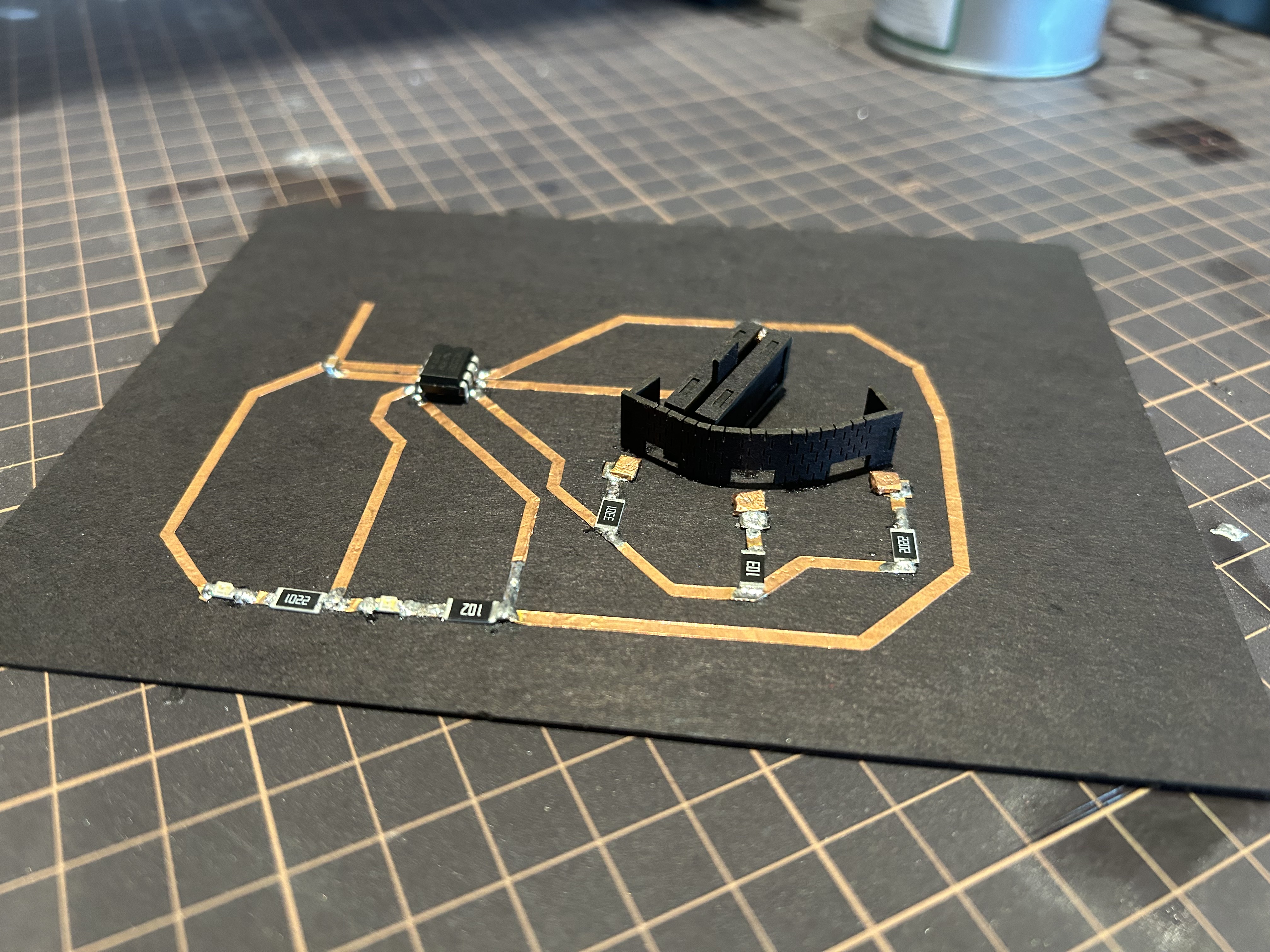
A KiCad-designed PCB with copper tapes as circuit and laser-cut cardboard as switches, used to connect with different resistors to change the blinking speed of 2 LEDs.
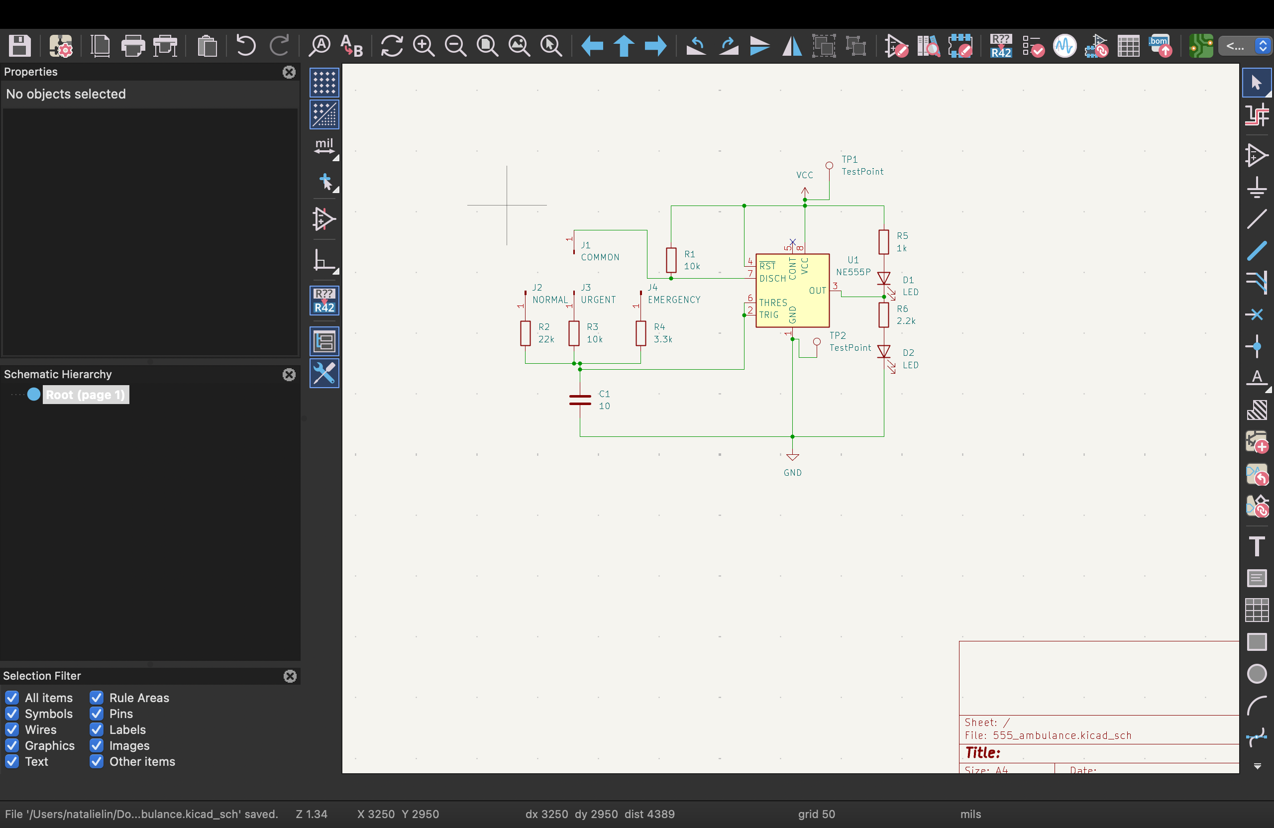
I desgined a circuit with a NE555 timer IC, 2 LEDs, 1 capacitor, and 6 resistors (2 of which are for the LEDs) to make the LEDs blink at different speeds. The circuit is first designed in Falstad, implemented in KiCad, printed with adhesive foil and Cricut, and then soldered onto a cardboard board.
Circuit design
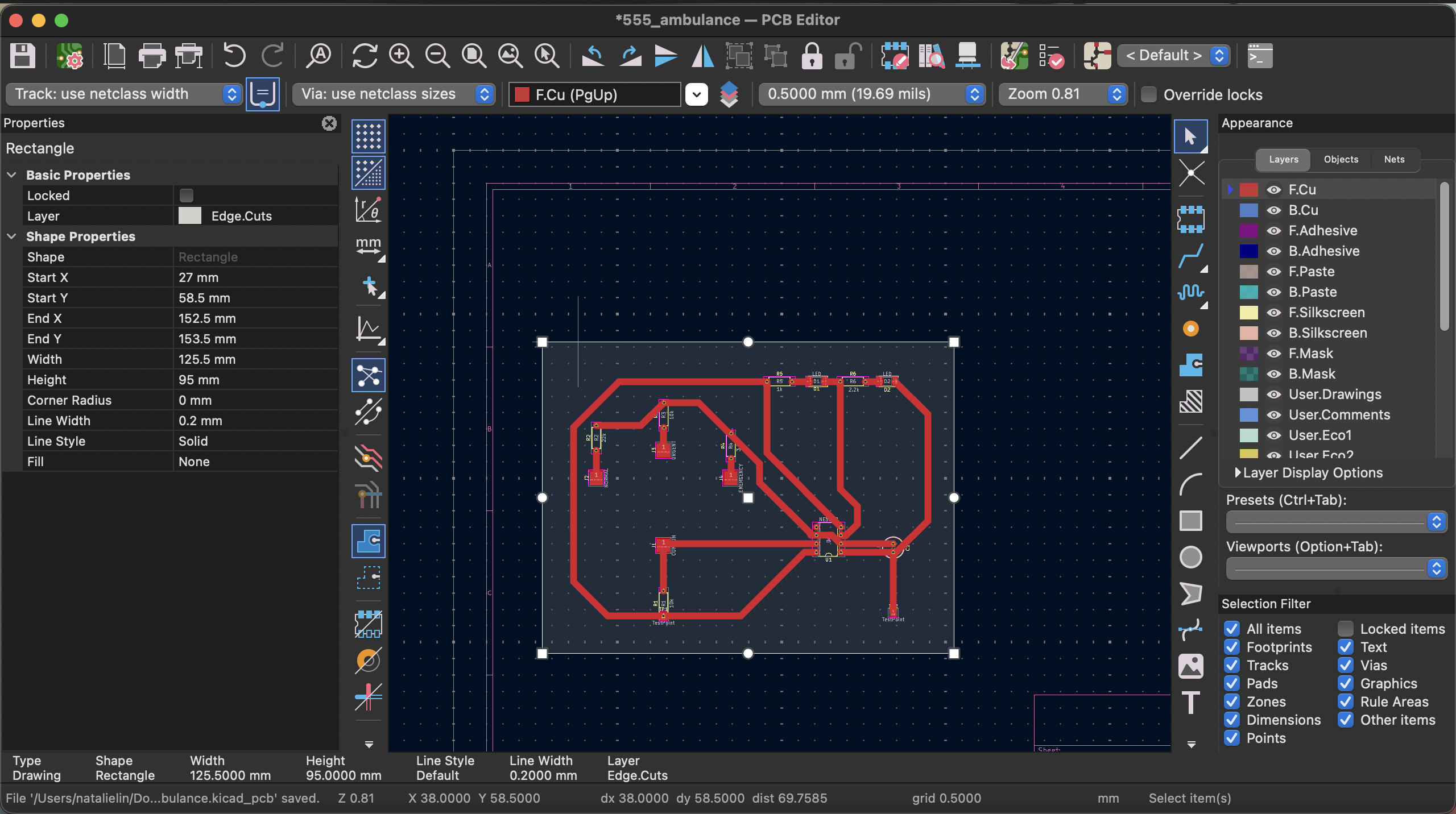
Dimension of the printed circuit
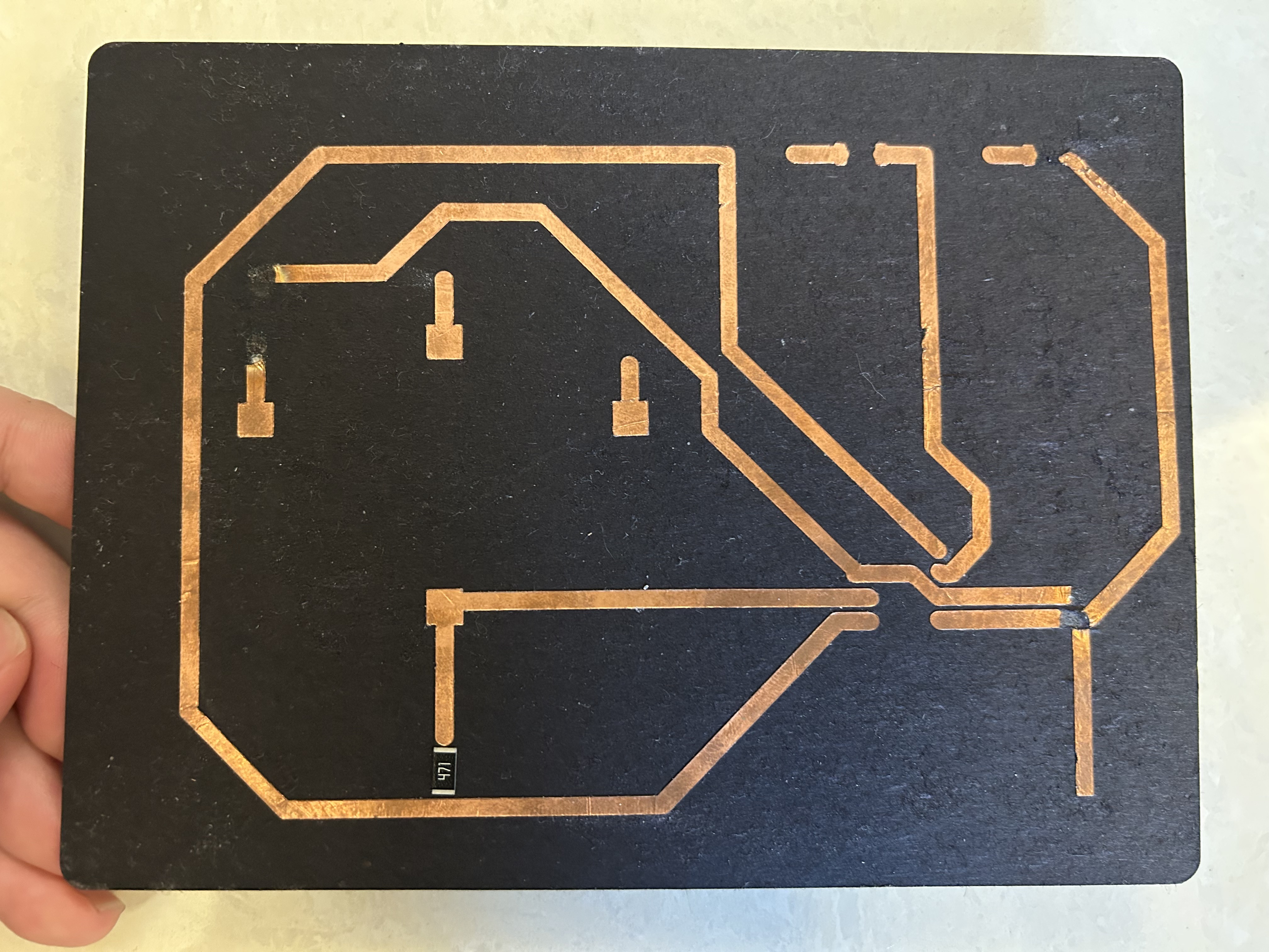
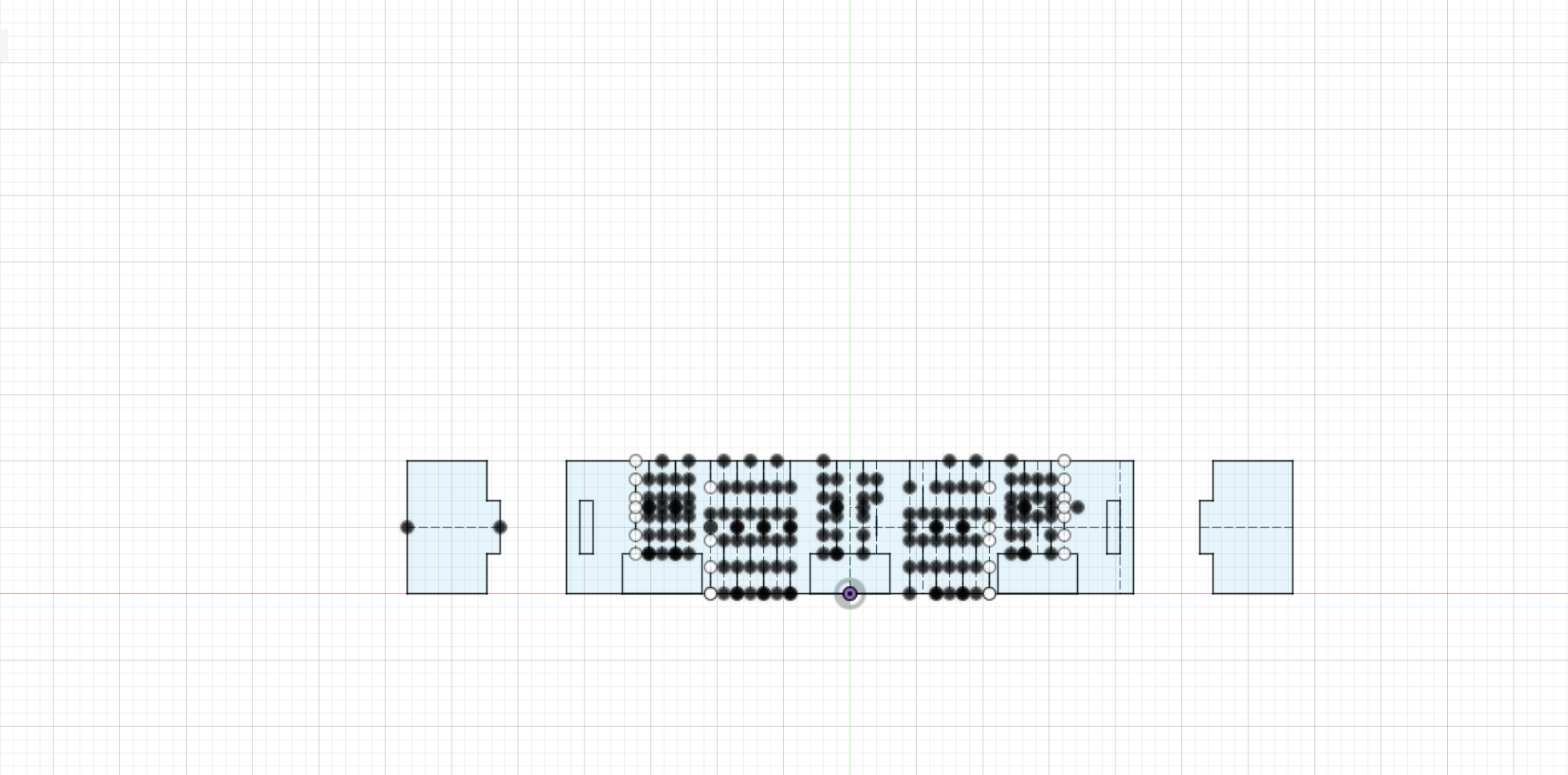
I mistakenly used the properties of the “Edge.Cuts” layer as the dimension of the printed circuit in Cricut, which is 95mm in width. The actual dimension of the circuit is 71.5mm in width. Though soldering the components onto the board is still possible, it resulted in a clustered soldering metal.
I checked y coordinate of the bottomost circuit (y = 142mm), and subtracted the y coordinate of the topmost circuit (y = 70.5mm), which is 71.5mm. I used the corrected width to scale the circuit in Cricut, and printed a new one, which is used in the final outcome.
Component selection
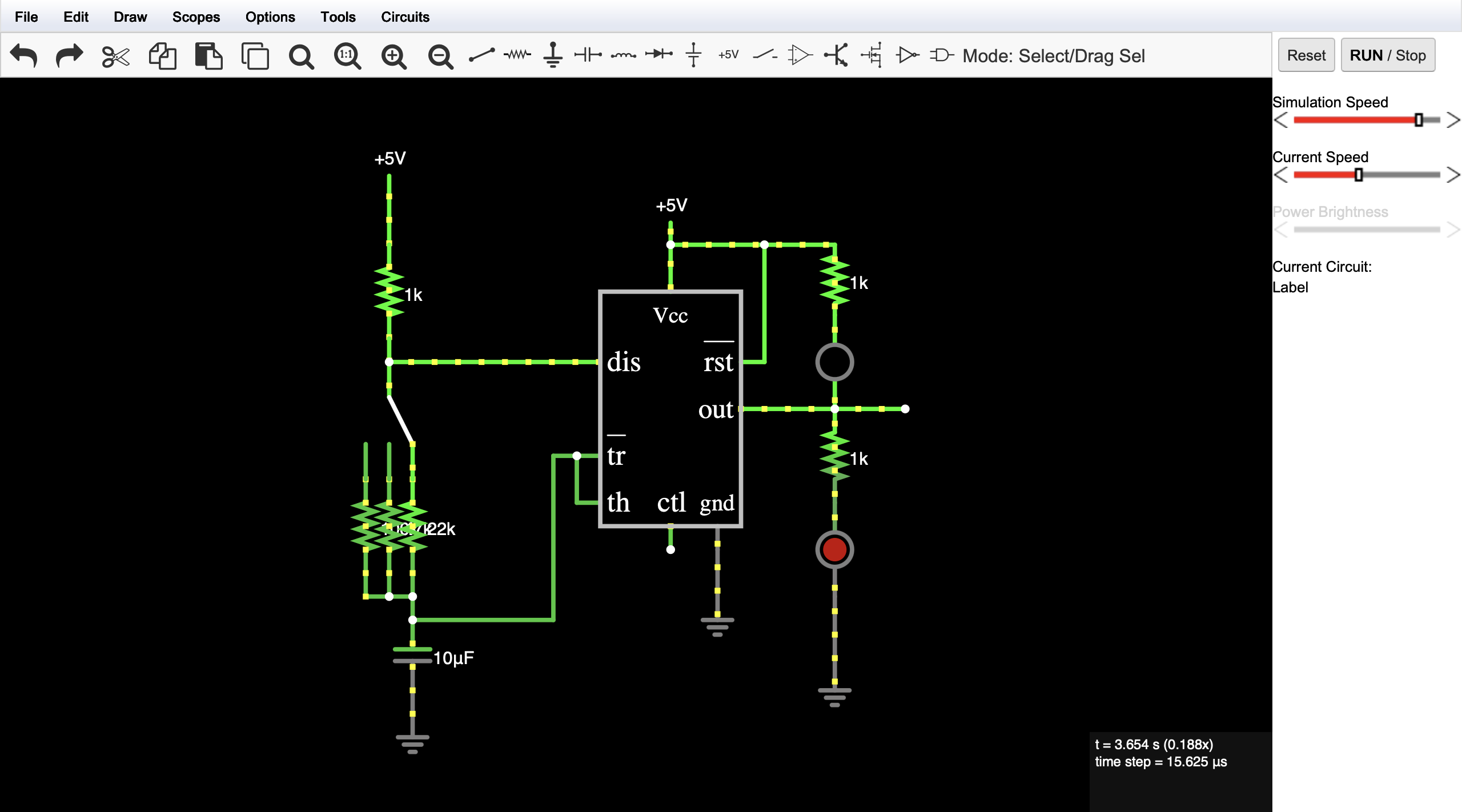
My initial design of the circuit used 6 resistors: 3x 1kΩ, 1x 22kΩ, 1x 47kΩ, and 1x 100kΩ. However, the resistors with the footprint I used in KiCad and >= 1kΩ are only available in 1kΩ, 2.2kΩ, 3.3kΩ, 10kΩ, 22kΩ.
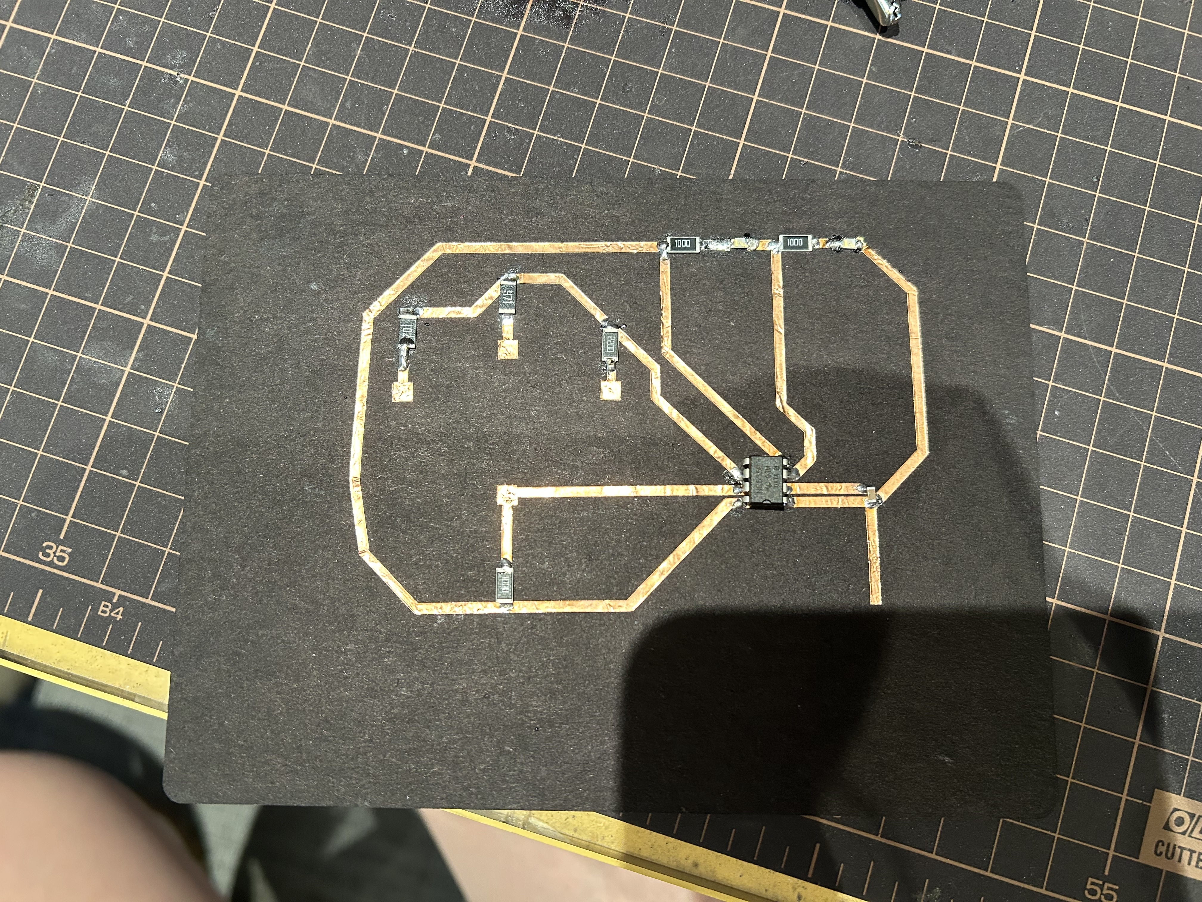
I initially thought scaling down the resistance of the resistors (e.g., 100kΩ to 1kΩ, 47kΩ to 470Ω, 1kΩ to 100Ω) would still work. However, the blinking speed of the LEDs is too fast to be observed. I desoldered the resistors and replaced them with 2x 22kΩ, 2x 10kΩ, 1x 3.3kΩ, and 1x 1kΩ, which resulted in a more observable blinking speed.
Switch design
First switch
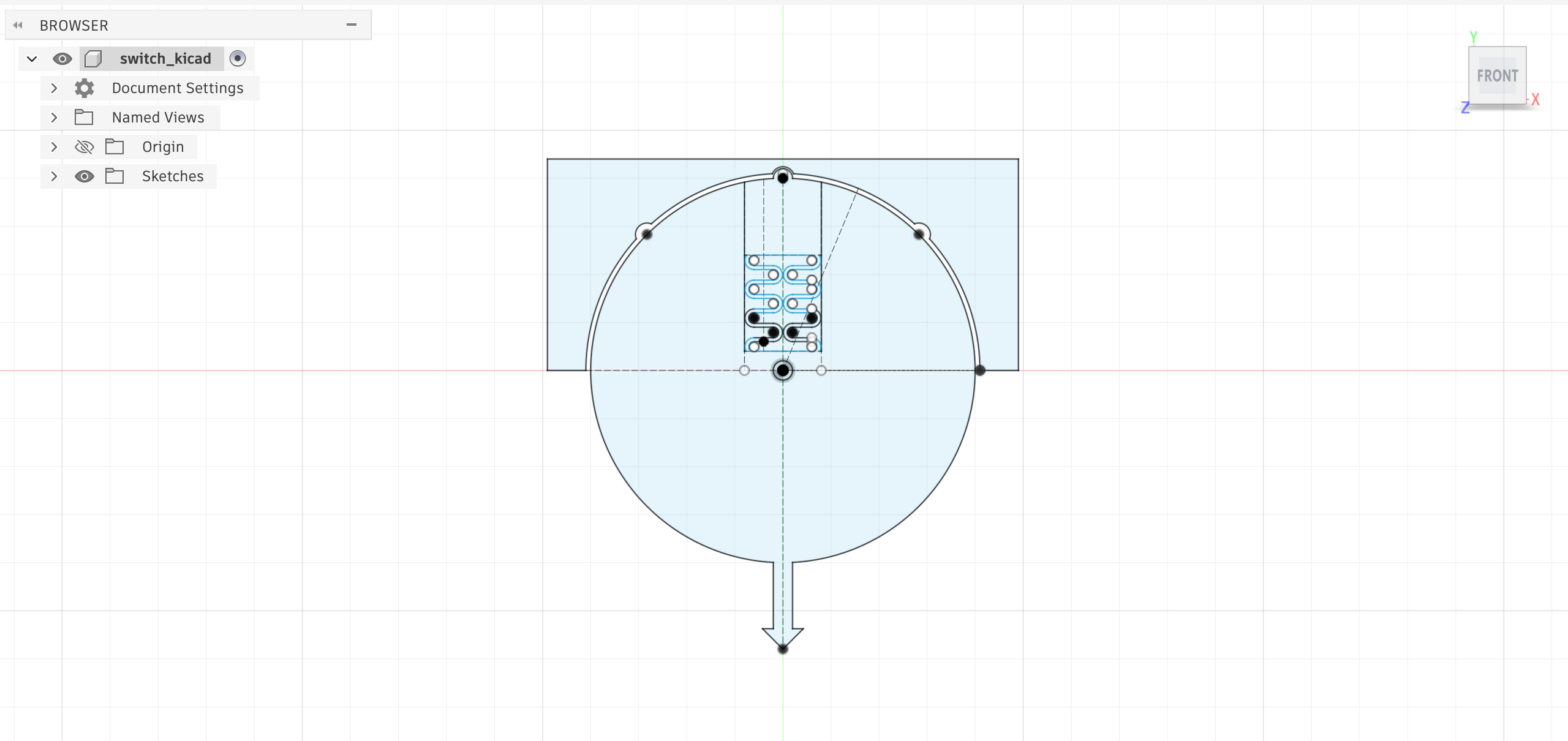
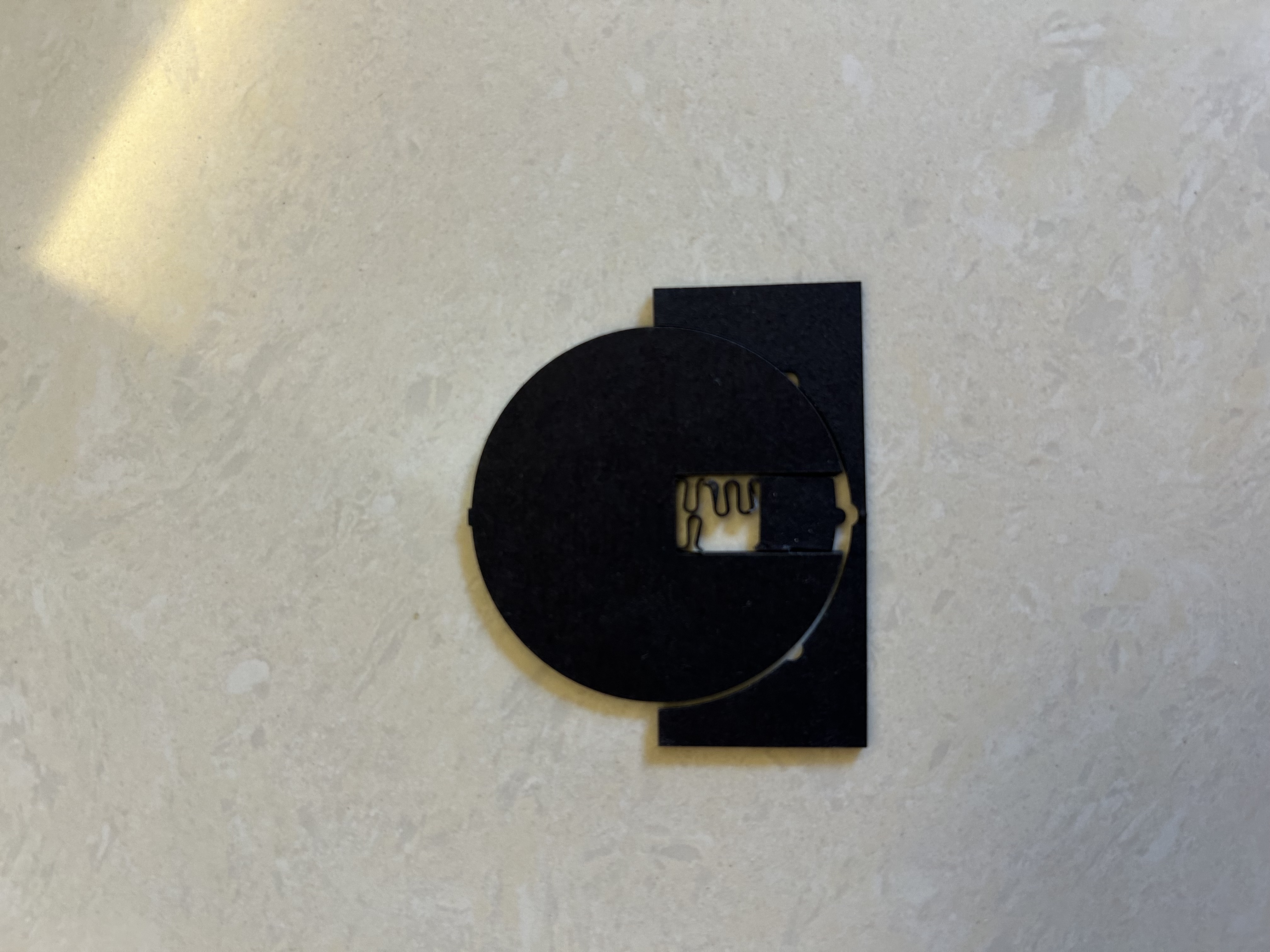
The idea of the first switch is to use a curly spring similar to the one I designed in the Fidget Toy project, so pressing the uncut part of the spring would deform the spring, making the circle turnable since the tip is not obstructed anymore, and releasing the spring would let the tip stop at the cut hole of the outer frame.
However, the cut cardstock wasn’t as elastic as PLA used in 3D printing, so the release didn’t make the tip bounce back as planned. In addition, the spring and the arrow were too thin and soft, so the spring broke after pressing it several times, and the arrow even broke after removing the cardstock from the laser cutter.
Second switch / Final switch
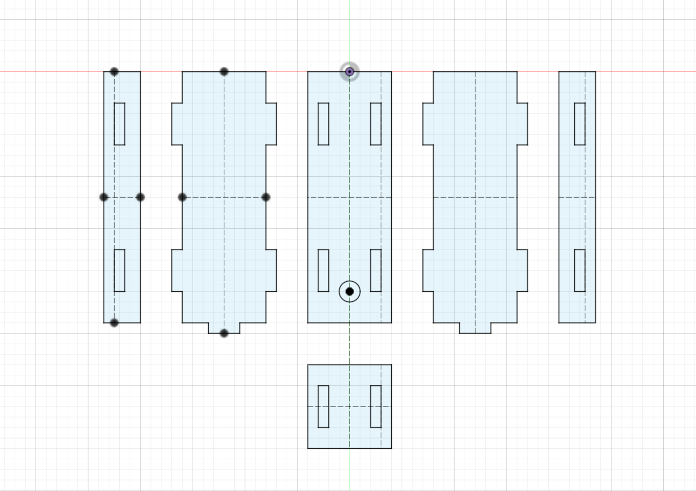
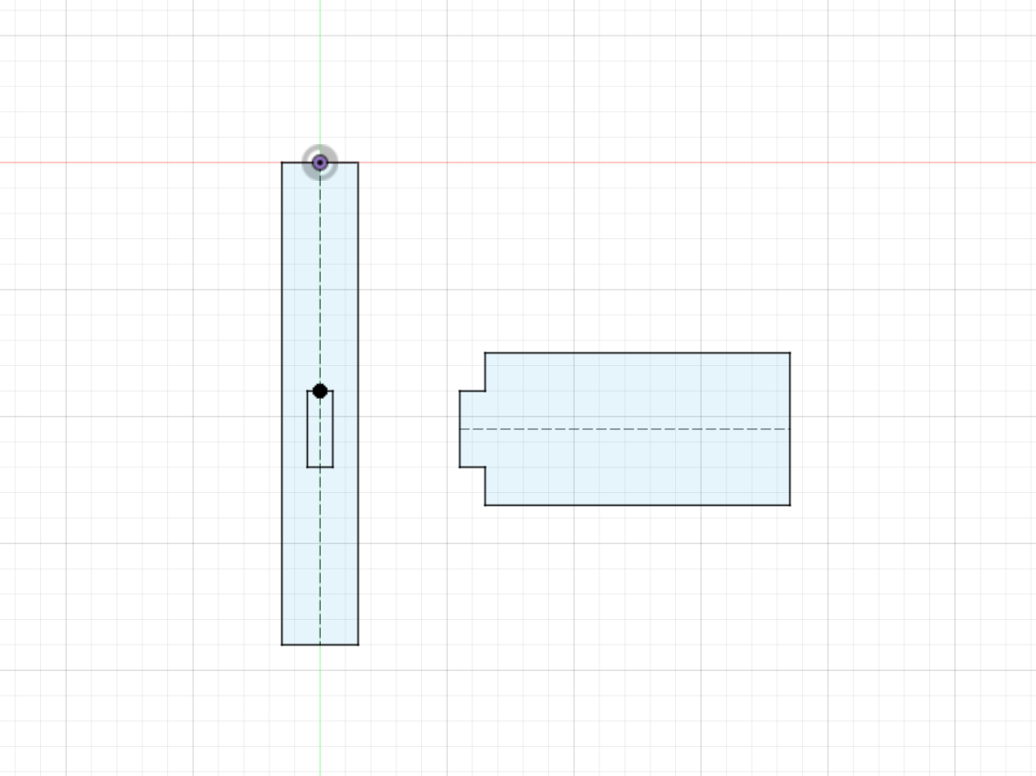
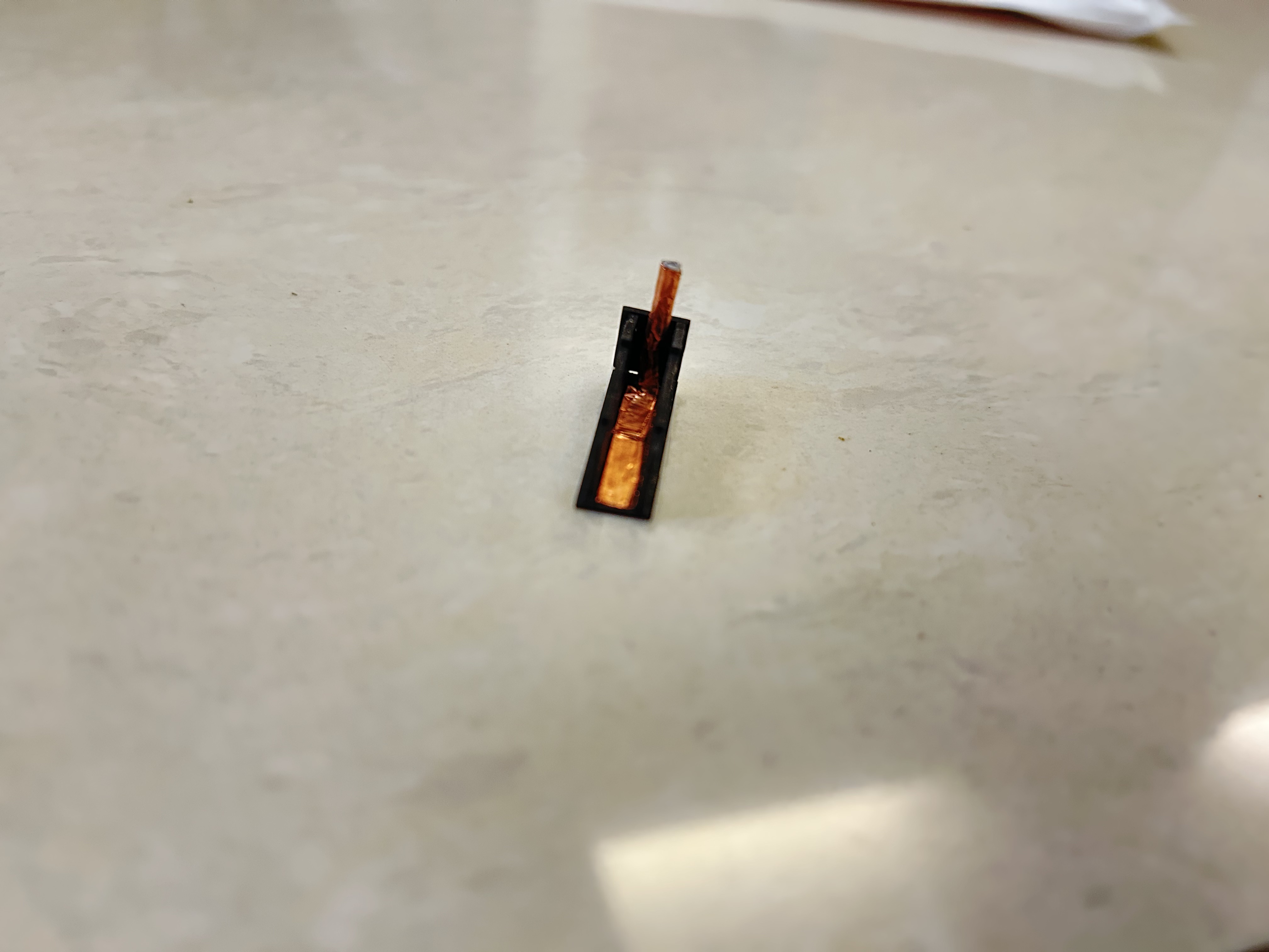
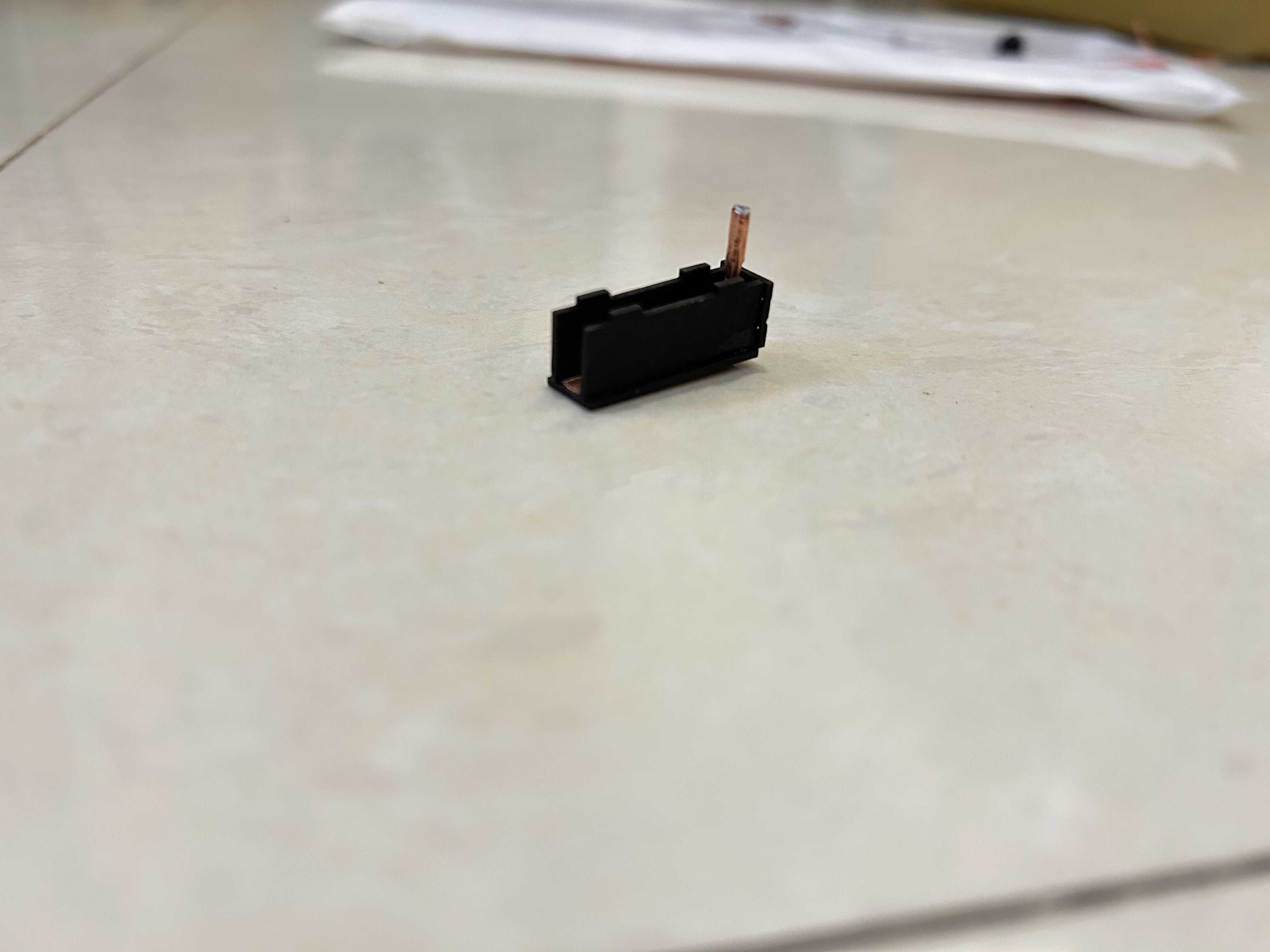
The axle is made by rolling the adhesive backing of the adhesive foil into a cylinder, and wrapping it with a thin strip of adhesive foil. The axle is then inserted into the hole of the rail. The inner side of the rail is also taped with adhesive foil to continue the circuit.
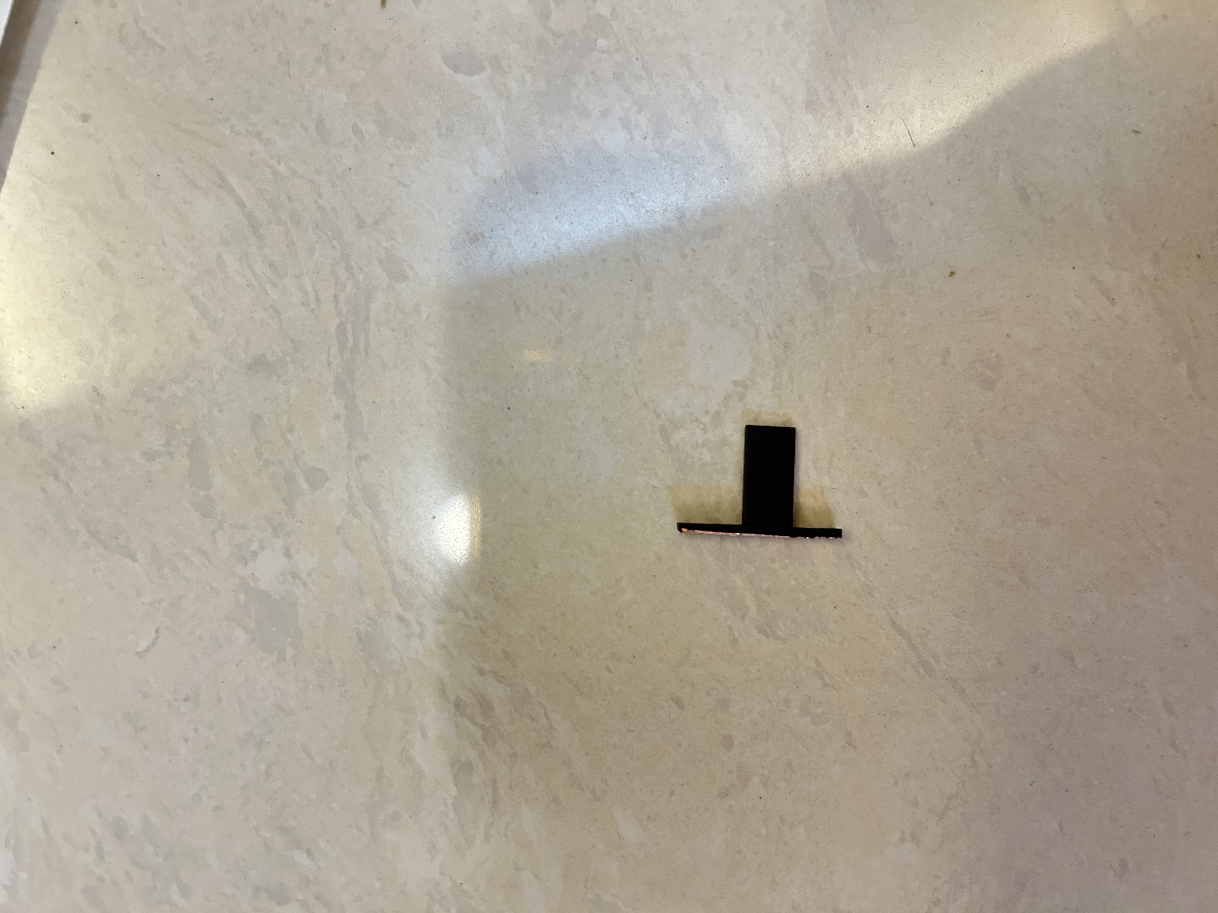
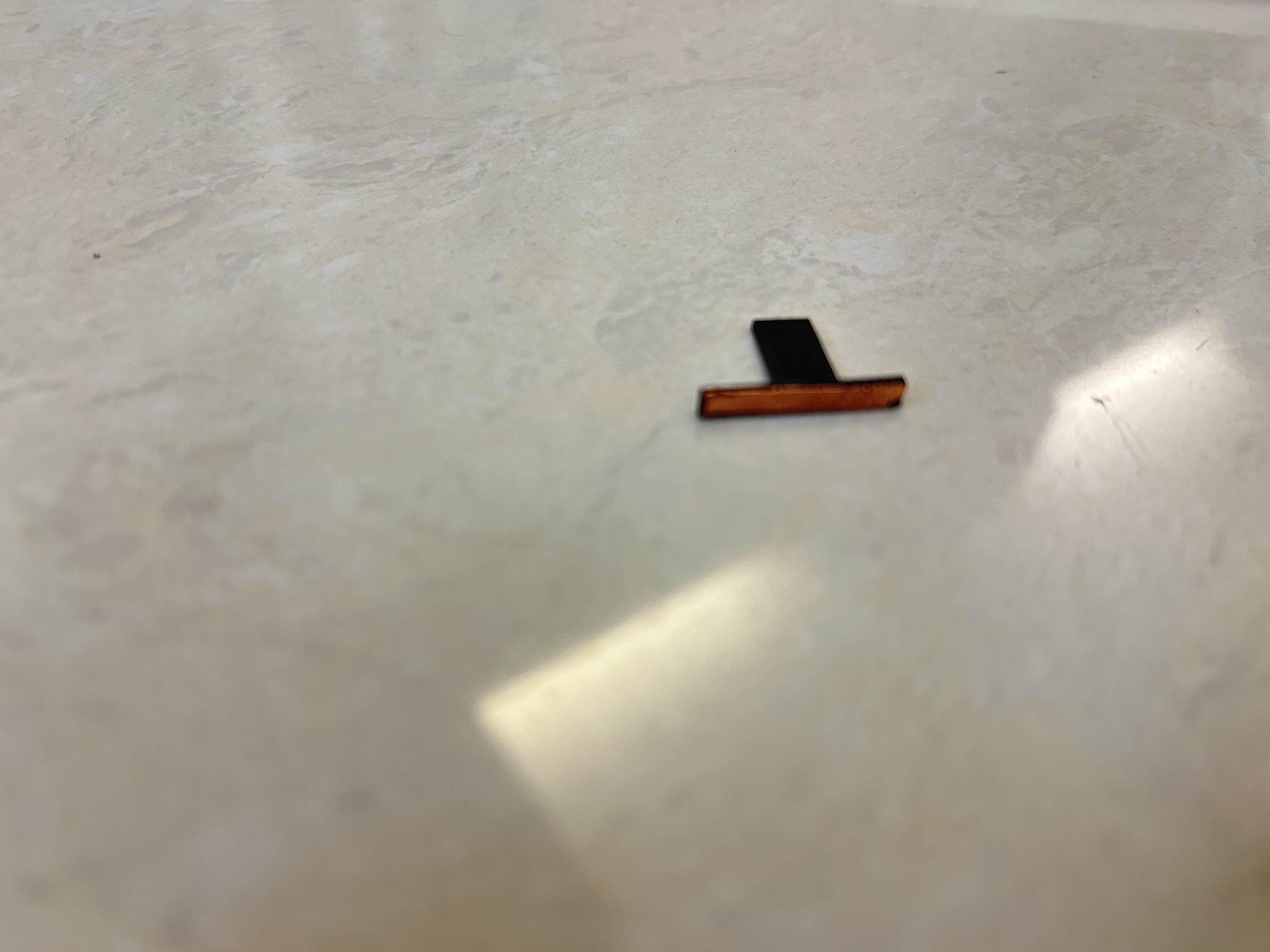
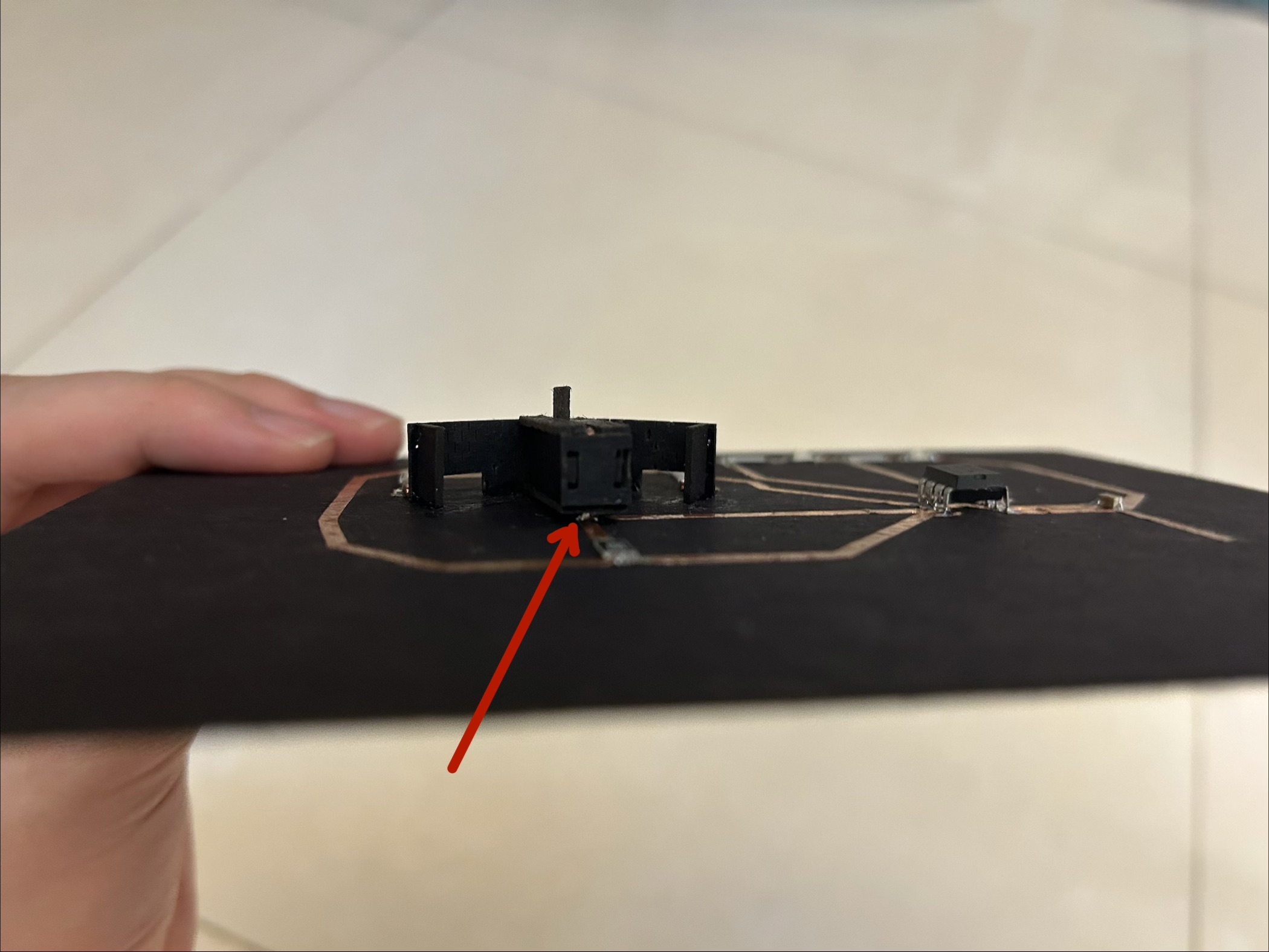
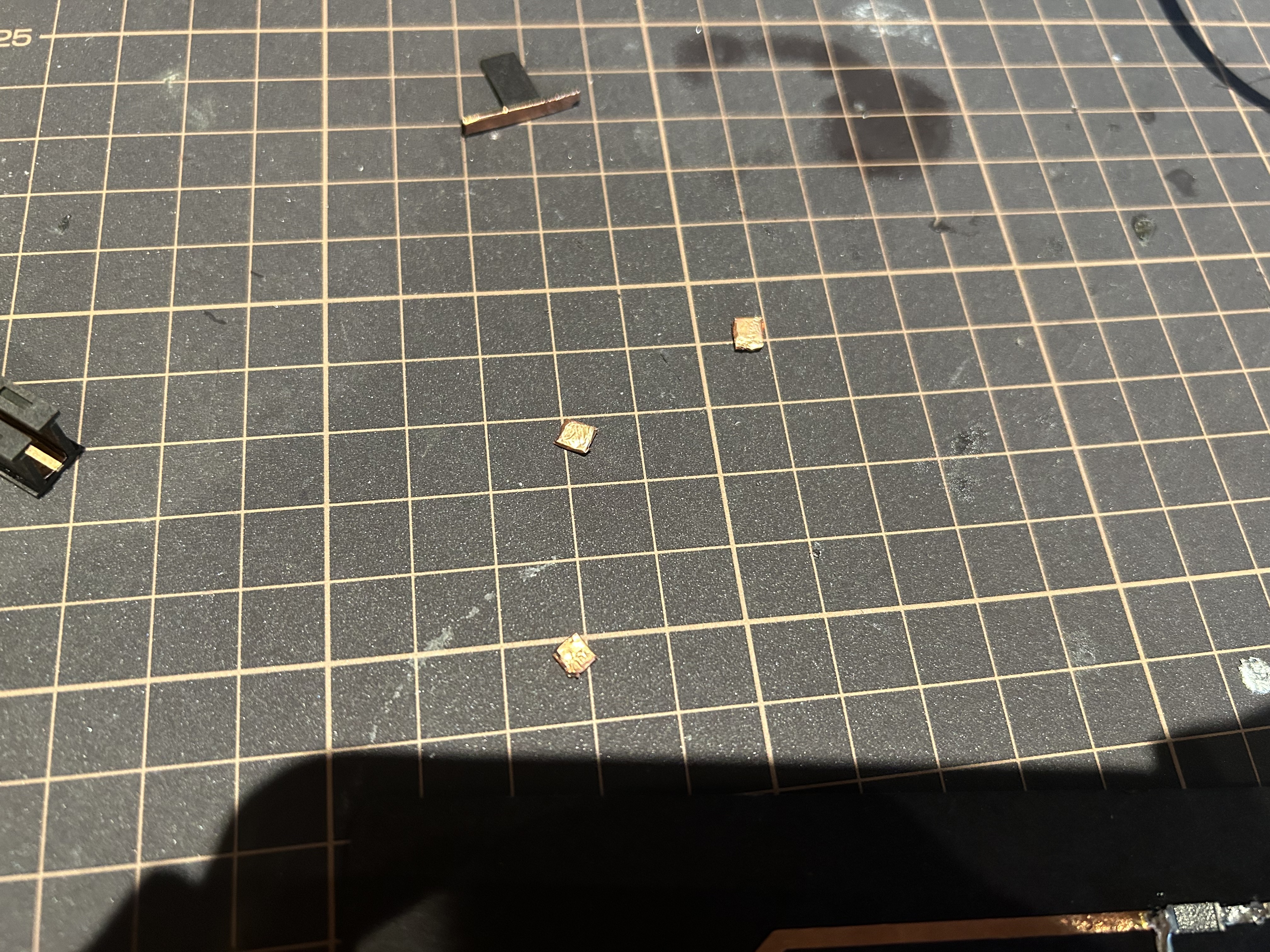
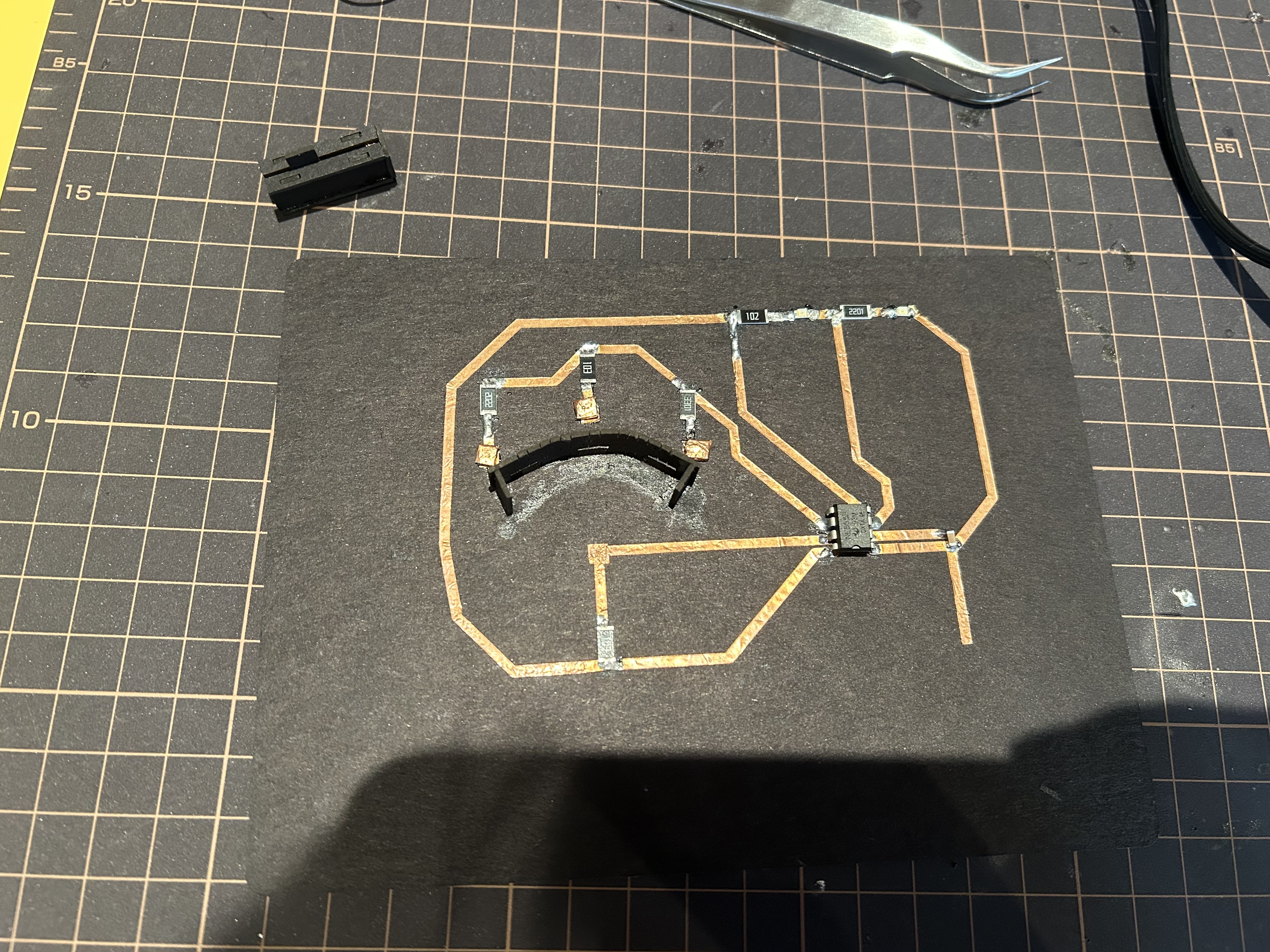
Since both the rail and the soldering of the axle increase the height of the stick, I padded the each testpoint of the 3 resistors with a cut piece of cardstock, wrapped it with adhesive foil, and soldered the square to the testpoint.
What I learned
- Do the exact measurements of the distance between components when designing the board.
- Check the materials available in the lab and design the circuit accordingly. Doing so avoids wasting time testing with different resistors, and unsoldering then resoldering the circuit. It also helps obtain a cleaner circuit and soldering.