Digital Piano
A pitch-controlled electronic instrument built with an NE555 timer, potentiometer, buzzer, and push button.
I built a simple pitch-controlled electronic instrument around an NE555 timer. Turning the potentiometer changes the oscillator frequency and therefore the pitch produced by the buzzer, and a push button controls when it sounds.
Final prototype

How it works
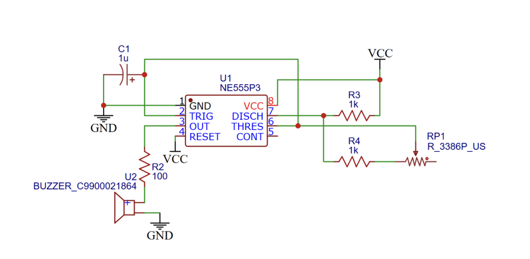
The NE555 is configured as an oscillator by connecting its TRIG (pin 2) and THRES (pin 6) inputs. The capacitor repeatedly charges and discharges through the timing resistances, causing OUT (pin 3) to alternate between high and low and generate a square wave.
The potentiometer makes up part of that timing resistance, so turning it changes the frequency of the square wave, and the buzzer’s pitch with it.
Starting point
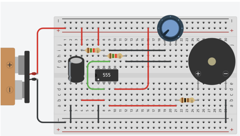
The class provided a circuit diagram and a working breadboard prototype in TinkerCAD, which I used as my starting point.
The TinkerCAD version worked, but its fixed component spacing led to several long or redundant connections. Before adding new behavior, I wanted to make the circuit easier to trace.
Design iterations
1. Simplifying the breadboard layout
My first change was organizational rather than functional. I removed unnecessary jumper wires when components could connect directly—for example, replacing a wire-resistor connection with the resistor itself—and shortened other component chains.
I also grouped related components into clearer rows and columns. The circuit behaved the same way, but the cleaner layout made its connections easier to follow and debug.

2. Adding visible feedback
Next, I tried replacing one of the 1 kΩ resistors with an LED so the circuit gave a visible cue as well as sound.
An LED isn’t electrically equivalent to a resistor, so the swap changed how the oscillator behaved, and I could watch that happen while turning the potentiometer.
By changing one of the resistors to an LED, firstly, the pitch range of the buzzer changed. The brightness of the LED also provided a visual indication of the current passed through, where a higher pitch (higher frequency) corresponded to a brighter LED. This allowed for a more intuitive understanding of the relationship between the potentiometer’s position and the resulting sound and light output.

3. Improving the interaction
In the earlier versions, I started and stopped the sound by making or breaking a connection with a loose wire. For the final iteration, I added a push button, so playing a tone is now just a press.
It’s a small circuit change, but it’s the one that made the prototype feel like an instrument someone could play instead of an electronics demo.
What I learned
Not every iteration needs to add functionality. The breadboard cleanup didn’t change what the circuit did, but it made the connections easier to reason about. The push button only controls a sound the circuit could already make, and that’s what made it playable.